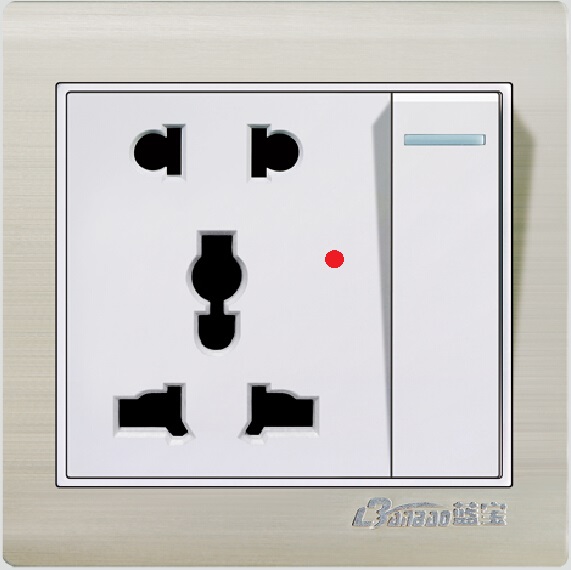
Aluminium socket 1gang 5pin with LED indicator
A 1 - gang 5 - pin socket with an LED indicator is a common electrical accessory, and its working principle mainly involves the power - supply part, the socket part, and the LED indicator part. The following is a detailed introduction:
- **Power - supply principle**: Connect the live wire (L) and the neutral wire (N) of the socket to the 220V AC power supply. Usually, the live wire is connected to one terminal of the internal switch of the socket, and the neutral wire is directly connected to the relevant terminal of the socket interface. After the switch is turned on, the 220V AC power can be supplied to the socket interface, providing electrical energy for electrical appliances connected to the socket.
- **Socket interface working principle**: The 5 - pin socket generally includes multiple AC power - supply interfaces, which are usually designed according to the standard electrical plug specifications, such as the common two - hole and three - hole sockets. These sockets are internally connected to the live wire and the neutral wire terminals. When the electrical plug is inserted into the socket, the pins of the plug are in good contact with the internal conductors of the socket, so that the electrical appliance is connected to the power supply circuit, and the electrical appliance can work normally.
- **LED indicator working principle**:
- **Common indicator circuit principle**: Usually, a high - resistance resistor is connected in series with the LED and then connected to the live wire and the neutral wire circuit. According to Ohm's law, the high - resistance resistor limits the current flowing through the LED to prevent the current from being too large and burning out the LED. When the socket is powered on, a small current flows through the LED, and the LED emits light to indicate that the socket is in the powered - on state.
- **Complex indicator circuit principle**: Some socket LED indicator circuits are more complex. For example, they may include components such as capacitors, diodes, transistors, and resistors. As shown in a certain design, after the 220V live wire voltage is stepped down by a capacitor, rectified by a bridge rectifier composed of diodes, regulated by a voltage - regulator diode, and filtered by a capacitor, a low - voltage DC is output. This low - voltage DC is used to charge a capacitor and control the on - off of transistors. When the capacitor is not fully charged, the transistor is turned on, and the LED lights up; after the capacitor is fully charged, the transistor is turned off, and the LED goes out, achieving the function of energy - saving indication. Pressing a button can also discharge the capacitor, making the transistor turn on again and the LED light up, so as to observe whether the socket is powered on at any time.